|
Depending on the working frequency used by the radar, antenna height
and spacing varies. For a working frequency of 27.65 MHz, antenna spacing
is 5.42 m (half the electromagnetic wavelength). The antenna height
of a full length quater-wave groundplane is 2.7 m. Below 25 MHz,
the antenna must be electrically shortened using a coil or a wound wire
to ensure enough mechanical stability to withstand stroms.
2.1. Transmit antenna
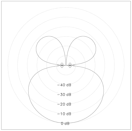
The transmit antenna consists of two rows of 2-element linear array antennas
with 0.5 Lambda spacing. The two rows are 0.15 Lambda apart. To form the
antenna pattern, the cables from the
power splitter to the antennas have to be cut to a specific length. The cables
A and D (to back row) have to be 0.35 Lambda shorter than the cables B and C
(to front row). The propagation speed factor for RG213/U is V = 0.66
and has been
taken into account for the calculations of the values given in the table below.

| Frequency |
0.5 Lambda |
0.15 Lambda |
Length difference A,D to B,C |
Cable length A,D |
Cable length B,C |
| 29.85 MHz |
5.03 m |
1.51 m |
2.32 m |
6.63 m |
8.958 m |
| 27.65 MHz |
5.42 m |
1.63 m |
2.51 m |
7.16 m |
9.678 m |
| 16.045 MHz |
9.35 m |
2.80 m |
4.32 m |
12.34 m |
16.66 m |
| 12.50 MHz |
12.00 m |
3.60 m |
5.54 m |
15.84 m |
21.38 m |
| 8.00 MHz |
18.75 m |
5.63 m |
8.66 m |
24.75 m |
33.41 m |
Note, that the length of cables A and D can be selected to some practical
value (to mechanically install the power amplifier at a convenient pace) and
cables B and C have to be 0.35 Lambda * V longer.
The null produced in the antenna pattern
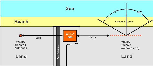
should point towards the receive
antennas to reduce the energy transmitted on the direct path from the
transmit to the receive antenna. The transmit power amplifier, which also
houses the power splitter, is located at the transmit antenna.
A 200 m long RG 213/U cable is required for
the transmit radio signal, a power cable (115/230 V, 3*2.5 mm²)
is required for operation of the power amplifier.
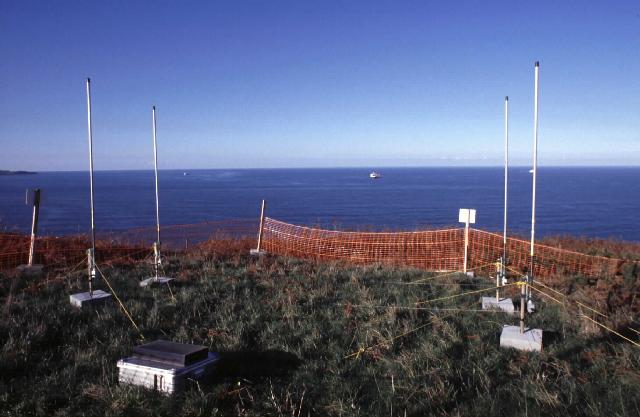
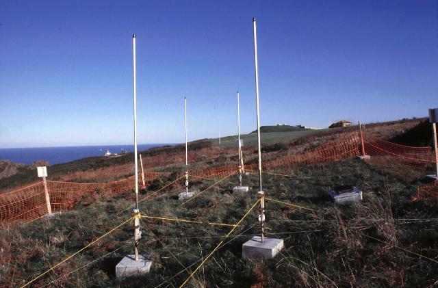
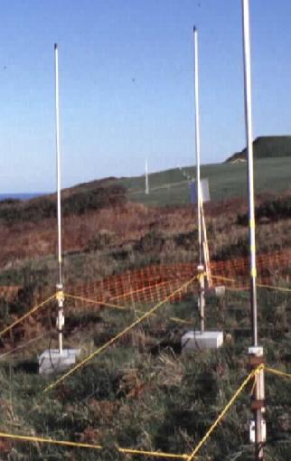
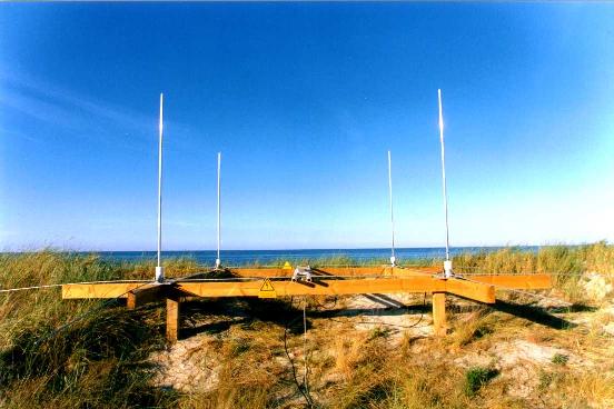
Here are photos of the transmit antenna installed at Gijon (Spain):
2.2 Receive antenna linear array
If sea state is to be measured, e.g. significant waveheight and wave
directional spectra, a 16-element linear array is required.
A 12-element linear array can also be used, but gives some coarser azimuthal
resolution. The total
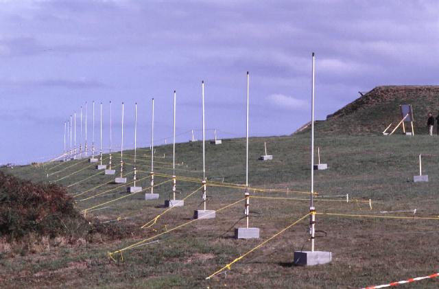
length of 16-element array is 15 * 5.42 m = 81.3 m at 27.65 MHz.
The antenna spacing and variances in height of the mounting points should be
within 1 % accuracy.
We often use wooden sticks of ~5 cm * ~8 cm to fix the
antennas to, so fine adjustments can be done during installation.
Each antenna is connected to a separate receiver channel, so 16 cables
RG 213/U, each 200 m long, adjusted to ±20 cm difference
in length, are required.
| Frequency |
Spacing |
16-element total length |
12-element total length |
| 29.85 MHz |
5.02 m |
75.38 m |
55.28 m |
| 27.65 MHz |
5.42 m |
81.23 m |
59.57 m |
| 16.046 MHz |
9.35 m |
140.22 m |
102.83 m |
| 12.50 MHz |
12.0 m |
180.0 m |
132.0 m |
| 8.00 MHz |
18.75 m |
281.25 m |
206.25 m |
The direction of the array is required to correctly map the measurements
to geographical coordinates.
This is done by passing "True North"
to the processing software.
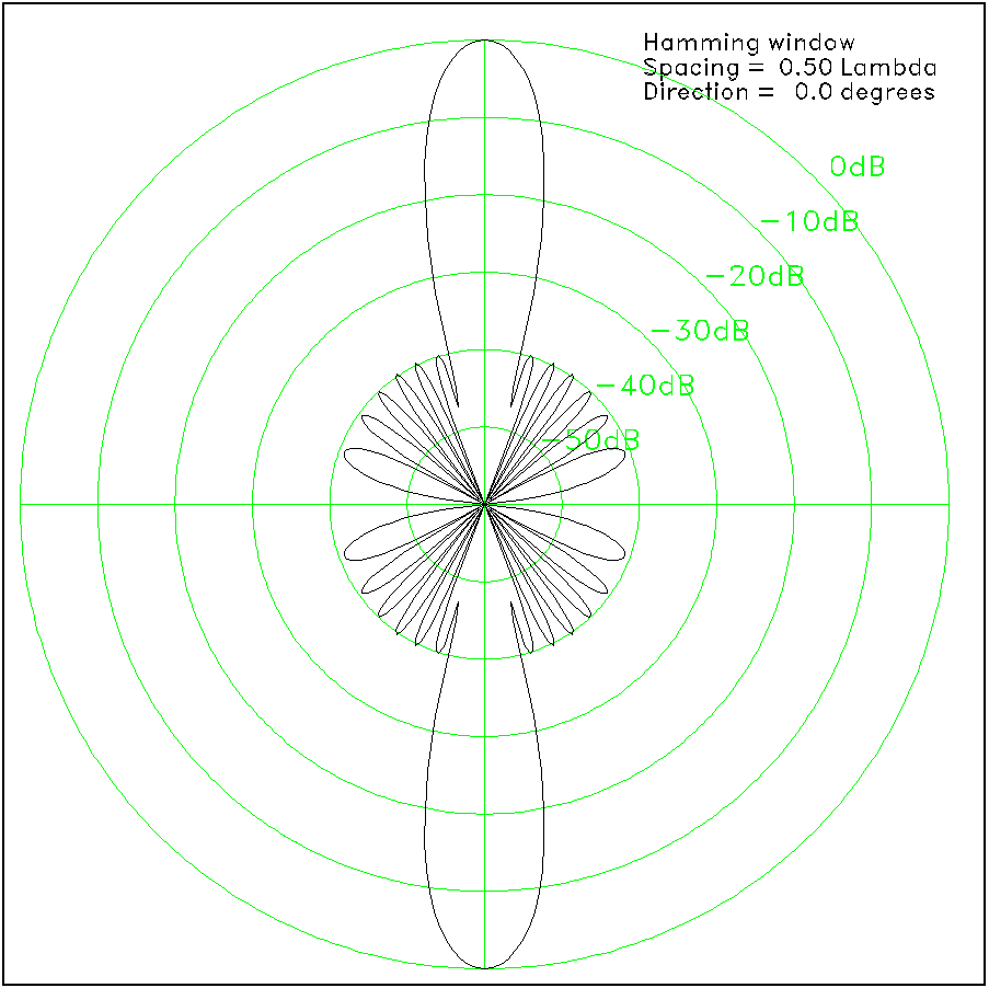
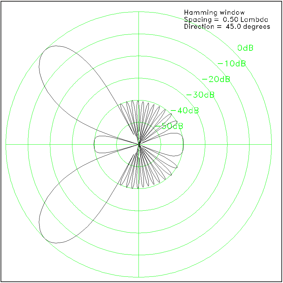
If the linear array is operated in beam forming mode, these are the
expected antenna patterns (beams) for 16 antennas when steering the beam to
0 degrees
(perpendicular to the array) or
45 degrees. Note, that due to the
reduced active aperture length, the beam gets wider when steered to the side.
2.3 Receive antenna square array
If only surface currents are to be measured, a small 4-element square array
at 5.42 m diagonal spacing (at 27.65 MHz) together with
a direction finding technique for azimuthal resolution may be used.
| Frequency |
Diagonal Spacing |
Square edge lengh |
| 29.85 MHz |
5.02 m |
3.55 m * 3.55 m |
| 27.65 MHz |
5.42 m |
3.83 m * 3.83 m |
| 16.046 MHz |
9.35 m |
6.61 m * 6.61 m |
| 12.506 MHz |
12.00 m |
8.48 m * 8.48 m |
| 8.00 MHz |
18.75 m |
13.26 m * 13.26 m |
The direction of the array is required to correctly map the measurements
to geographical coordinates.
This is done by passing "True North"
to the processing software.
|